
The 500 mA Source Measure Unit delivers precision pulsed current with exceptional pulse fidelity for accurate LED, VCSEL, and laser diode characterization. With nanosecond rise and fall times and hardware-controlled timing synchronization, it ensures precise alignment between source, measurement, and external instrumentation.
Key Features
- Pulse width range: 10 μs (01 μs or 50 μs option) to 15000 s
- Max DC output power: 200 W
- Max pulsed output power: 200 W
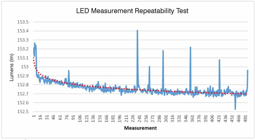
- Clean pulse shapes
- Minimal distortion
- High repeatability
Applications

DC and Pulse Current
Precision pulsing is key to best practices testing criteria. With duty cycle 0 to 100%, the 500 mA Source Measure Unit offers pulse width flexibility with models supporting fast pulses (to 1 μs) to long pulses (15,000 s). Pulse width accuracy is 1μs with pulse rise and fall times of 200 ns to 3 μs. Ramp time is adjustable based upon device characteristics.
LIV Curves
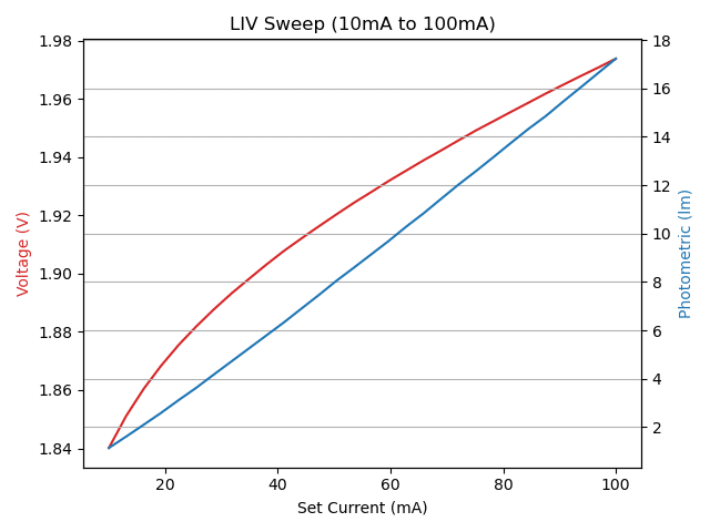
LIV curves provide a complete view of device performance by combining light output, current, and voltage into a single, time-aligned measurement. Using precision pulsed SMU technology, engineers can accurately characterize efficiency, threshold behavior, and overall device performance with minimal thermal distortion.
Peak Wavelength
Peak Wavelength is one of the many characterization capabilities offered when Vektrex SMU is paired with a spectrometer or photodiode.
500 mA Source Measure Unit Specifications
| 500 mA Source Measure Unit Specifications | 500 mA (Max Current) |
|---|---|
| Overall | |
| Min Output Voltage | 0 V |
| Max Compliance Voltage | 50 V, 100 V, 200 V, 400 V |
| Source Channels | 1 |
| Max DC Output Power | 200 W |
| Max Pulsed Out Power | 200 W |
| 500 mA Source Measure Unit Specifications | 500 mA (Max Current) |
|---|---|
| Pulsing | |
| Pulse Width Range | 10 μs (01 μs or 50 μs option) to 15000 s |
| Pulse Width Resolution | 0.1 μs (11 ns w/ Pulse Width Offset) |
| Pulse Width Accuracy | 1 μs (50 ns w/ Pulse Width Offset) |
| Pulse Rise/Fall Time | 200 ns – 3 μs |
| Typical Pulse Width Jitter | 30 ns |
| Timebase Accuracy | 50 ppm |
| Pulse Period Range | 11 μs – 30000 s, depending on model |
| Duty Cycle Range | Programmable 0-100%, no current limits, limited by Toffmin of 20 μs or 9 μs (1 μs model) |
| Pulse Count | 0-12000000 (Multiple Pulse and Pulsed Sweep modes) |
| Sweep Steps | 3-10000 (Pulsed Sweep mode) |
| Low Range Current | |
| Max Current | 40 mA |
| Setpoint Resolution | 1 μA |
| Output Current Accuracy | 0.05%+ 0 μA |
| Min Recommended Current | 10 μA |
| High Range Current | |
| Max Current | 500 mA |
| Setpoint Resolution | 1 μA |
| Output Current Accuracy | 0.05%+75 μA |
Digitizer Specifications
| Digitizer Channels | 1,2 |
| Measure Method | 4 wire |
| Ranges | 3 Ranges, 10 V, 100 V and 400 V |
| Input Impedance | 1 MΩ–1.4 MΩ |
| Disconnect Relay | Disconnect Sense +/- terminals when Digitizer is placed in 0 V range |
| Coupling | DC Coupled, All Ranges |
| Maximum Common Mode | Sense+ or Sense- must be < 420 VDC from Chassis Ground or Force+ or Force- |
| ADC Sample Rate | 500,000 samples/second, continuous sampling |
| Digitizer Type | True differential |
| Resolution | 18 Bits |
| Programmable Measurement Aperture | 2 μs to 400 ms, 500 kHz samples boxcar averaged to form measurement points |
| Measurement Trigger | Software or hardware |
| Hardware Trigger Edge Polarity | Programmable |
| Trigger Delay | Programmable 0 to 400 ms, 2 μs resolution |
| Measurement Points Per Acquisition | 1 to 525 |
| Autozero Function | Reduces measurement offset |
| Sampling Method | Logarithmic sampling to 1000 s, and custom programmable sampling available with +BIAS option |
Digitizer Range Specifications
| Ranges | 10 V | 100 V | 400 V |
|---|---|---|---|
| Maximum Voltage | 10.4 V | 112.2 V | 420.6 V |
| Typical Noise, RMS | 100 μV | 200 μV | 500 μV |
| Bandwidth (-3 dB) | 570 kHz | 290 kHz | 570 kHz |
| Accuracy | 0.03%+300 μV | 0.09%+3 mV | 0.06%+30 mV |
General SpikeSafe SMU Specifications
| Current Out | |
| Digitizer Channels | 1,2 |
| Output Current Drive Type | Floating, both + and – terminal driven, max 100 V common mode to chassis ground |
| Output Cabling | Single or multi-conductor twisted pair |
| Recommended Max Output Cable Length | 6 m |
| Trigger In | |
| Signal Type | 5 V logic, VIH > 3.5 V, VIL < 1.5 V |
| Polarity | Programmable |
| Modes Supported | Multiple Pulse, Pulsed Sweep, Modulated Current |
| Programmable Delay | Programmable delay, 10 μs to 30 s |
| Delay Programming Resolution | 1 μs |
| Delay Jitter | Multiple Pulse Mode: 3.4 μs, Pulsed Sweep Mode: 107 μs |
| Trigger Out | |
| Signal Type | 5 V logic, 50 Ω pull-up and open drain outputs |
| Polarity | Programmable |
| Modes Supported | All pulsed modes, Software trigger in DC mode |
| Trigger Jitter | < 10 ns typical |
| Programmable Delay | Programmable delay, 10 μs to 30 s |
| Miscellaneous | |
| Nominal Current Ripple | 0.01%+160 μA |
| DC Ramp Rate: Low Speed Setting | 10 V/s, 50 mA/s |
| DC Ramp Rate: Default Setting | 10 V/s, 500 mA/s |
| DC Ramp Rate: High Speed Setting | 1000 V/s, 50 A/s |
| Current Stability | 70 ppm |
| SpikeSafe Transient Protection | Power shutdown timing ns. (voltage monitor accuracy: 3% +1 V | current monitor accuracy: model dependent) |
| Other External Factors | |
| General Purpose Input (EXT_GPI) | Optoisolated input, generates External Pause SYST:ERR? Event, VLow Max: 0.75 V, VHigh Min: 2.72 V, VHigh Max: 27.2 V |
| Remote Disable (Interlock) | Optoisolated input, halts output, selectable polarity, VLow Max: 0.75 V, VHigh Min: 2.72 V, VHigh Max: 27.2 V |
| General | |
| Physical | Rack mount/bench top chassis 1/2 Rack 89 mmH x 213 mmW x 452 mmD Weight: 8 lbs, 3.6 kg |
| Input Power | AC 100-240 VAC, 700 W, Single Phase |
| Remote Control | 100-base T Ethernet, TCP/IP with SCPI syntax |
| Monitoring System | Built-in acquisition system monitors & reports voltage, current, and fault conditions |
| Device Protection | 3rd generation SpikeSafe protection including high-speed over current shutdown, slow start up, leakage detection and other protection algorithms |
| Calibration Interval | 1 year calibration interval recommended |
| Operating Conditions | For indoor use only, 10 C to 35 C, < 2000 m altitude |
| Cooling | Air cooled |
| Particulate Level | Clean lab conditions |
| Other | CE, ROHS, ISO17025 certification |
Add-Ons
Operating Modes
| Operating Mode | Description | Typical Application |
|---|---|---|
| Bias | Constant DC bias current – generally used for SVF (voltage sensitivity factor) determination. | Thermal Resistance and Tj measurements. Bias may be added to many operating modes. Requires purchase of optional BIAS. |
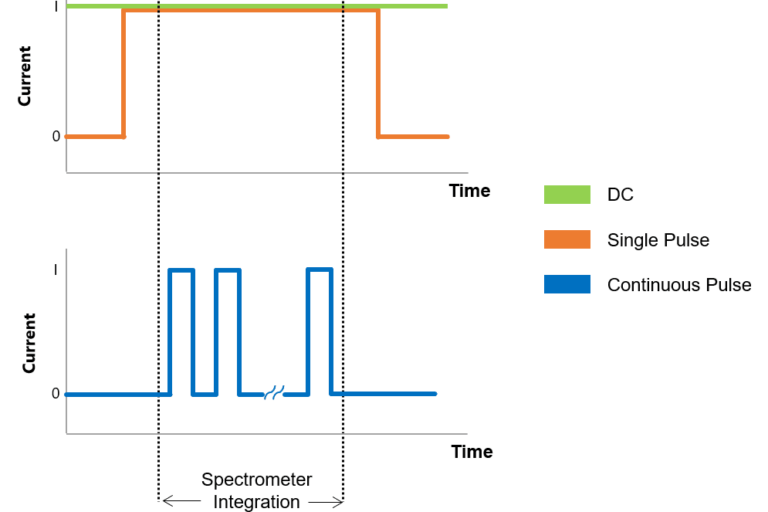
| Continuous Dynamic | Continuous pulse train – current changes may occur while the source channel is enabled. | PWM, production binning, closed-loop power control. |
| Continuous Pulse | Continuous current pulse train that transitions on and off according to configured pulse parameters. | Continuous pulse light measurements to reduce junction heating. Any other continuous pulse application. |
| CW Sweep | Constant wave current sweep. | Typical characterization test where output parameters like power are monitored over a range of input power levels. |
| DC | Direct current. Also known as constant current or constant wave. DC dynamic mode allows current to be changed +/- during DC operation. | Any constant current application. LM-85, light measurement, characterization, R&D, production. |
| DC Dynamic | Constant current – current changes may occur while the source channel is enabled. | Low speed > 10 s pulsing. Software controlled pulsing. Useful for TEC control. |
| Modulated Current | A programmable sequence of DC current steps that define a waveform. Sequences may be finite or run indefinitely. | Cell phone flash emulation, rectifier ripple emulation. Requires purchase of optional Modulated Current function. |
| Multiple Pulse | Similar to Single Pulse mode, but allows a programmable number of pulses to be output. | Fixed pulse count device testing. Also recommended for Single Pulse use (1 pulse). |
| Multiple Pulse Burst | Multiple bursts of pulses with defined pulse and burst timing, and current changes. | Burst L-I-V sweeps, high duty cycle sweeps. |
| Pulsed Sweep | Also known as QCW (quasi-constant wave). Primarily used to minimize self-heating such as with I-V, L-I, and LIV curves. Pulsed sweep on/off may be used to thermally stress devices or speed lifetime test. Also used for withstand or limit testing. Step number reported at error used to identify failure current. | I-V plots for LEDs, lasers, and other semiconductors. L-I plots for optoelectronics, overcurrent protection circuit tests, pulse withstand testing. |
| Repetitive Burst Mode | Multiple bursts of bursts. | VCSEL testing. Customer specific applications. |
| Single Pulse | Also known as mono pulse. One pulse output (one transition on and off) according to configured pulse parameters. | Any single pulse application. LM-85, light measurement, characterization, R&D, production. |
Contact Us
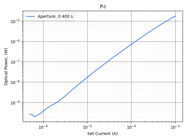
Accurate currents combined with fast rise and fall times plus a precision hardware-controlled timing system that synchronizes source, measure and external instrumentation allow for discovery at low currents.
News & Articles

Related Software
💡 Python and API Examples
💡 Control Panel Software Application