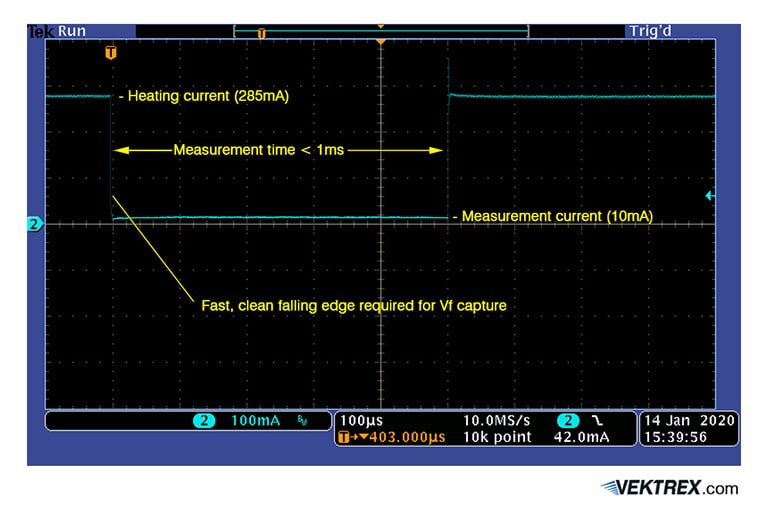
Tj Measurement is most accurate when using JEDEC’s Electrical Test Method (ETM), described in JESD-51-14 and JESD-51-51. This method uses the LED or laser’s forward voltage (Vf) vs temperature characteristic to infer temperature. This process requires a special two-level current waveform. An example is shown below. In the ETM a high, heating current level, powers the device at full power in order to heat it to its operating junction temperature. After the temperature is reached, the current is then reduced to a low measurement level. Voltage readings are taken at the measurement level and these are compared with reference readings to determine the junction temperature.
While the method is straightforward, it requires high performance instrumentation to meet critical requirements in several areas. Some critical requirements for TJ Measurements are shown in the following graphic.
Related Downloads
💡 Meauring LED Junction Temperature (Tj)
Related Software
💡 Python API and Examples
💡 Control Panel Software Application
💡 TJ Measurement Toolkit
Example Electrical Test Method (ETM) Current Waveform
- Fast current fall times are required for the transition from heating to measurement current levels. The JEDEC ETM requires the transition to be within microseconds. If the transition is slower than that, voltage measurements just after the transition will be lost and the resulting Tj measurement may be too low. Most general-purpose SMUs don’t support such fast transitions. The bias source included in the Tj Toolkit transitions in a few microseconds.
- The ETM current waveform is a very high duty cycle (typically 99.9% or higher) pulsing waveform. Pulsed SMUs and pulsed current instruments typically rely on stored energy, and so their maximum duty cycle is quite limited – typically to less than 2.5%. Vektrex SMU products feature Continuous Power Conversion (CPC) technology. CPC continuously feeds power to the SMU’s pulse circuitry, allowing it to support any duty cycle with no limitations.
- In-situ Tj measurements and ensemble Tj measurements often involve high voltages, sometimes well over 100V. Most data acquisition hardware cannot handle such high voltages. Instruments, like sampling voltmeters, that can, often don’t have the necessary sampling speed or bandwidth to collect an accurate waveform. The SpikeSafe SMU digitizer has 18-bit resolution with up to 400V input capability. In addition, the it includes a true-differential balanced front end that dramatically reduces common mode noise. The SMU’s digitizer can easily resolve and record the millivolt and sub-millivolt voltage trends needed for the ETM projections – even in a high voltage ensemble circuit.
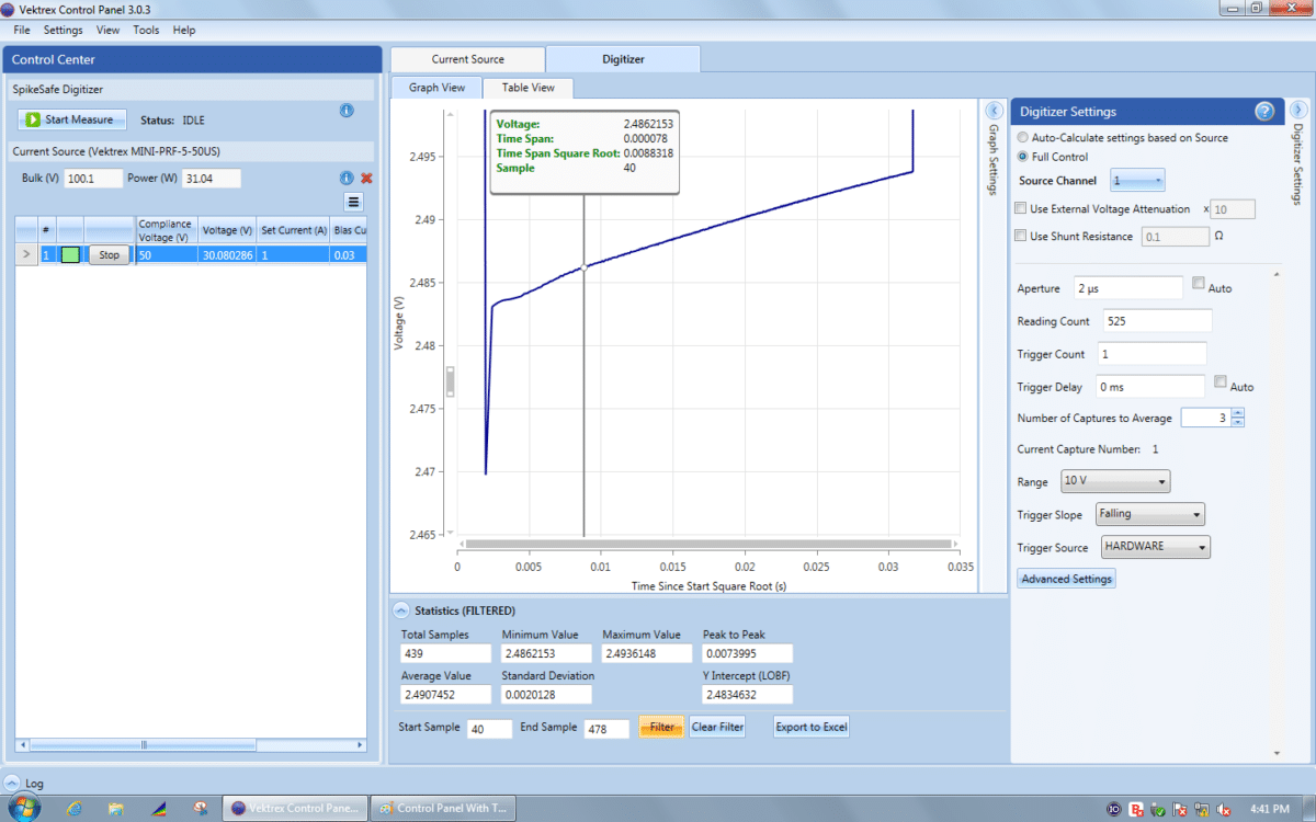
- Even with the right instrumentation, collecting the Vf sample data, visualizing trends and performing the necessary extrapolations is time-consuming and error prone. The Tj Measurement Toolkit includes an upgraded Control Panel software application that simplifies and automates these tasks. It features tools for current source/digitizer control, waveform capture and visualization, waveform averaging, and a tool that graphs the captured waveform on a square-root-of-time scale and projects the Vf trend. No programming is required.
- The Tj Measurement Toolkit provides training materials and instructions that simplify and explain the ETM. The training material includes an example Excel spreadsheet that does the final comparison and junction temperature calculation.
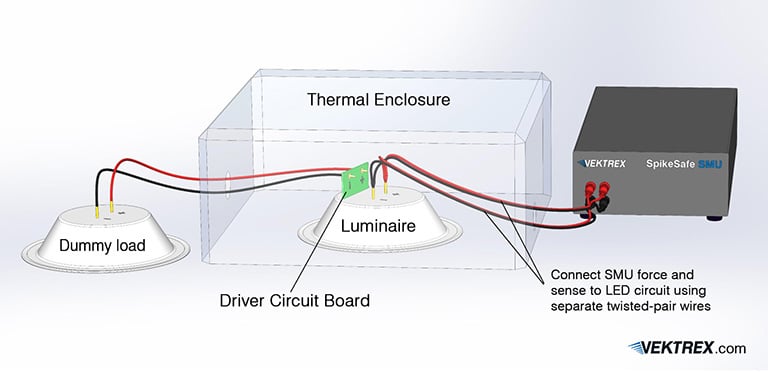
Easy connections, non-invasive testing
The figure below shows how easy it is to connect the SpikeSafe SMU to a luminaire to make in-situ Tj measurements. The luminaire’s driver circuit is disconnected from the LED circuit and instead connected to a dummy load. This ensures that the heat generated by the driver circuit is included in the measurement. The LED circuit is then driven by the SpikeSafe SMU using its Force + and Force – outputs. The Measure + and Measure – SMU inputs are connected to the LED or LEDs to be measured. The luminaire is usually placed in a temperature enclosure or a simulated installation site to provide the correct ambient temperature.