
The 20 A High Current Source Measure Unit (PSMU-HC-20) supplies precision DC, continuous pulse, and single pulse current with excellent pulse fidelity. Output pulses have fast rise and fall times – key to precise and repeatable LED, LIDAR, and VCSEL photometric and electrical measurements. A precision hardware-controlled timing system supports pulse widths from 1 µs to 15000 s. Continuous power conversion means no duty cycle or pulse width limitations. In addition to robust current capability, it features a low noise, true differential digitizer optimized for component testing.
Key Features
- Continuous Power Conversion – no duty cycle limitations
- Maximum voltage to 200V
- Maximum current to 20A
- DC and Pulse modes
- Repeatable time-aligned measurements
20 A High Current SMU Capabilities
Pulse Scope Shot
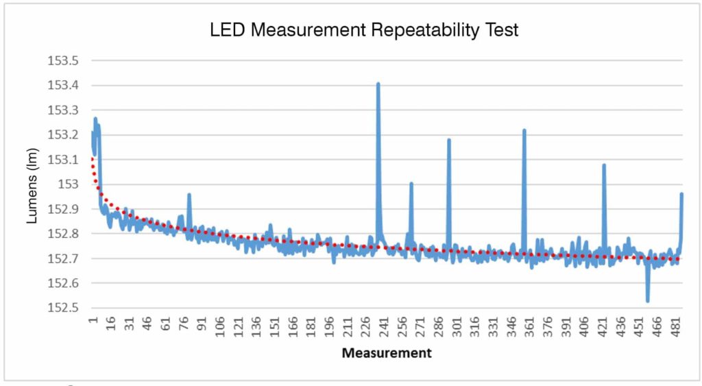
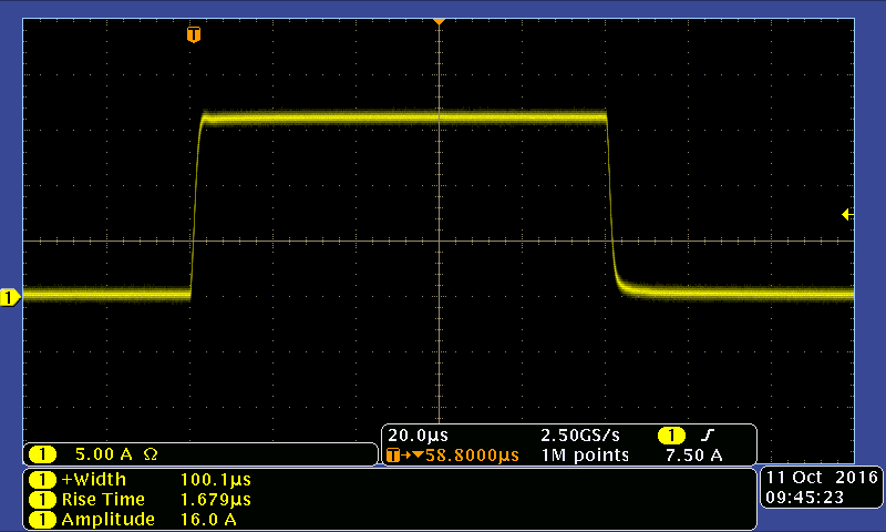
Precision pulsing is key to best practices for measurement repeatability. The 20 A Source Measure Unit offers programmable pulse width flexibility. It is capable of long pulse widths (ms to seconds) and short pulse widths (100 μs pulse widths and faster). Pulse width accuracy is 1.3 μs with nanosecond pulse rise and fall times.
Graphic shows 20 A current pulse @ 44.7 V 100 μs pulse width 1680 ns rise time
Low Noise Digitizer
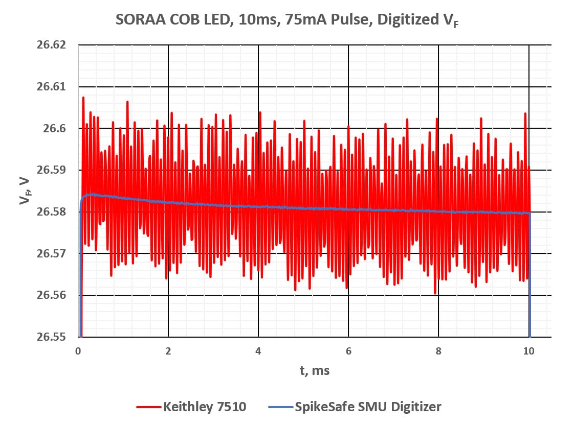
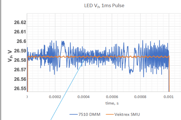
The High Current SMU features a low noise, true differential digitizer optimized for component testing. This digitizer can sample device Vf at 500 ksps and pick up millivolt changes in voltage that occur during pulsed operation. This sensitivity supports the most accurate IES LM-85-23 and CIE 225 measurements. Other instruments, that rely on single-ended circuitry, suffer from high common mode noise, making accurate measurements difficult or impossible. It easily measures a 4 mV Vf shift associated with 0.2 C of device heating in a high-power device.
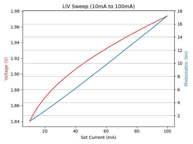
LIV Curves
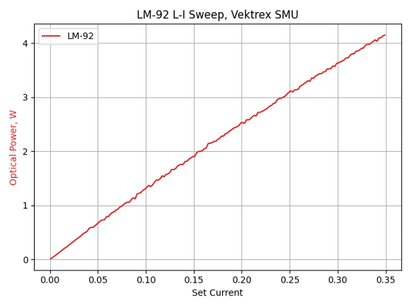
LIV curves provide a complete view of device performance by combining light output, current, and voltage into a single, time-aligned measurement. Using precision pulsed SMU technology, engineers can accurately characterize efficiency, threshold behavior, and overall device performance with minimal thermal distortion.
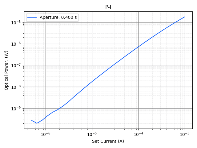
Optical Power Measurement
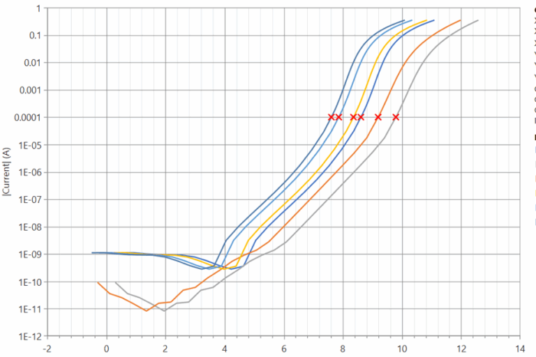
Accurately characterizing micro-LEDs, VCSELs, and sub-threshold semiconductor device sweeps requires ultra-low noise floors and tight timing synchronization. Standard SMUs often introduce common-mode noise that obscures faint optical outputs, distorting critical turn-on characteristics. Our Pulsed SMU solutions deliver exceptional measurement sensitivity down to sub-microamp drive currents, allowing engineers to capture smooth, highly repeatable P-I (Power-Current) curves down into the sub-nanowatt range.
20 A High Current SMU Measurements
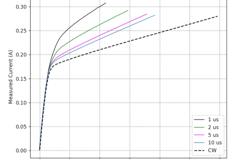
Measurements
CW Sweep
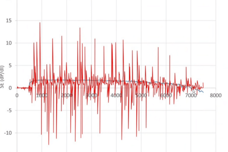
Measurements
Slope Efficiency Measurement
Source Measure Unit
Curve Trace Tool – VEKTREX
Junction Temperature (Tj)
Use Junction Temperature Measurement to Improve Lifetime Projections and Reduce Cost
20 A High Current SMU Specifications
| 20 A High Current SMU Specifications | 20 A (Max Current) |
|---|---|
| Overall | |
| Min Output Voltage | 0 V |
| Max Compliance Voltage | 200 V |
| Source Channels | 1 |
| Max DC Output Power | 3.2 kW |
| Conversion Mode | Buck/Boost |
| 20 A High Current SMU Specifications | 20 A (Max Current) |
|---|---|
| Pulsing | |
| Pulse Width Range | Model dependent; minimum (1 μs, 10 μs or 50 μs) to 15000 s |
| Pulse Width Resolution (w/Pulse Width Offset) | 0.1 μs (11 ns) |
| Pulse Width Accuracy (w/Pulse Width Offset) | 1.3 μs (50 ns) |
| Pulse Rise/Fall Time | 350 ns – 4.5 μs |
| Typical Pulse Width Jitter | 30 ns |
| Timebase Accuracy | 50 ppm |
| Pulse Period Range | 30 μs – 30000 s, depending on model |
| Duty Cycle Range | 0 – 100% |
| Pulse Count | 0-12000000 (Multiple Pulse and Pulsed Sweep modes) |
| Sweep Steps | 3-10000 (Pulsed Sweep mode) |
| Low Range Current | |
| Max Current | 800 mA |
| Setpoint Resolution | 20 µA |
| Output Current Accuracy | 0.04%+700 µA |
| Min Recommended Current | 700 µA |
| High Range Current | |
| Max Current | 20 A |
| Setpoint Resolution | 400 µA |
| Output Current Accuracy | 0.08%+4 mA |
Digitizer Specifications
| Digitizer Channels | 1,2 |
| Measure Method | 4 wire |
| Ranges | 3 Ranges, 10 V, 100 V and 400 V |
| Input Impedance | 1 MΩ–1.4 MΩ |
| Disconnect Relay | Disconnect Sense +/- terminals when Digitizer is placed in 0 V range |
| Coupling | DC Coupled, All Ranges |
| Maximum Common Mode | Sense+ or Sense- must be < 420 VDC from Chassis Ground or Force+ or Force- |
| ADC Sample Rate | 500,000 samples/second, continuous sampling |
| Digitizer Type | True differential |
| Resolution | 18 Bits |
| Programmable Measurement Aperture | 2 μs to 400 ms, 500 kHz samples boxcar averaged to form measurement points |
| Measurement Trigger | Software or hardware |
| Hardware Trigger Edge Polarity | Programmable |
| Trigger Delay | Programmable 0 to 400 ms, 2 μs resolution |
| Measurement Points Per Acquisition | 1 to 525 |
| Autozero Function | Reduces measurement offset |
Digitizer Range Specifications
| Ranges | 10 V | 100 V | 400 V |
|---|---|---|---|
| Maximum Voltage | 10.4 V | 112.2 V | 420.6 V |
| Typical Noise, RMS | 100 μV | 200 μV | 500 μV |
| Bandwidth (-3 dB) | 570 kHz | 290 kHz | 570 kHz |
| Accuracy | 0.09%+500 µV | 0.09%+2 mV | 0.09%+10 mV |
General SpikeSafe SMU Specifications
| Current Out | |
| Digitizer Channels | 1,2 |
| Output Current Drive Type | Floating, both + and – terminal driven, max 100 V common mode to chassis ground |
| Output Cabling | Single or multi-conductor twisted pair |
| Recommended Max Output Cable Length | 6 m |
| Trigger In | |
| Signal Type | 3.3 V logic (5 V tolerant) |
| Polarity | Programmable |
| Modes Supported | Multiple Pulse, Pulsed Sweep, Modulated Current |
| Programmable Delay | Programmable delay, 10 μs to 30 s |
| Delay Programming Resolution | 1 μs |
| Delay Jitter | Multiple Pulse Mode: 3.4 μs, Pulsed Sweep Mode: 107 μs |
| Trigger Out | |
| Signal Type | 5 V logic, 50 Ω pull-up and open drain outputs |
| Polarity | Programmable |
| Modes Supported | All pulsed modes, Software trigger in DC mode |
| Trigger Jitter | < 10 ns typical |
| Programmable Delay | Programmable delay, 12 μs to 30 s |
| Miscellaneous | |
| Nominal Current Ripple | <5A: 0.05%+250 μA >5A: 0.02%+1.8 mA |
| DC Ramp Rate: Low Speed Setting | 10 V/s, 200 mA/s |
| DC Ramp Rate: Default Setting | 10 V/s, 2 A/s |
| DC Ramp Rate: High Speed Setting | 1000 V/s, 200 A/s |
| Current Stability | 70 ppm |
| SpikeSafe Transient Protection | Power shutdown timing ns. (voltage monitor accuracy: 3%+1 V | current monitor accuracy: model dependent) |
| Other External Interfaces | |
| Remote Pause | Optoisolated input, pauses output, selectable polarity |
| Remote Disable | Optoisolated input, halts output, selectable polarity |
| General | |
| Physical | Rack mount/ bench top chassis 89mmH x 483mmW x 635mmD (including handles) |
| Input Power | AC Power: Selectable; single and three phase available; 50-60 Hz |
| Remote Control | 100-base T Ethernet, TCP/IP with SCPI syntax |
| Monitoring System | Built-in acquisition system monitors & reports voltage, current, and fault conditions |
| Device Protection | 3rd generation SpikeSafe protection including high-speed over current shutdown, slow start up, leakage detection and other protection algorithms |
| Calibration Interval | 1 year: on-site or return to Vektrex |
| Operating Conditions | For indoor use only, 10 to 35C, 70%R.H., <2000m altitude |
| Cooling | Air cooled |
| Particulate Level | Clean lab conditions |
| Other | CE, ROHS |
Add-Ons
Operating Modes
| Operating Mode | Description | Typical Application |
|---|---|---|
| Bias | Constant DC bias current – generally used for SVF (voltage sensitivity factor) determination. | Thermal Resistance and Tj measurements. Bias may be added to many operating modes. Requires purchase of optional BIAS. |
| Continuous Dynamic | Continuous pulse train – current changes may occur while the source channel is enabled. | PWM, production binning, closed-loop power control. |
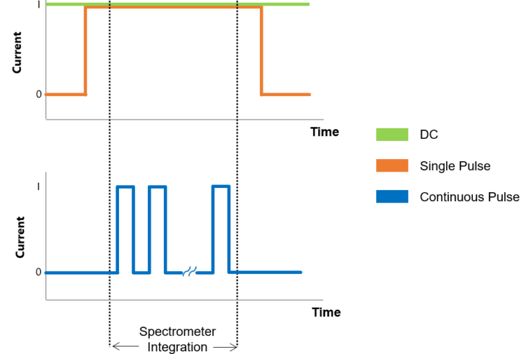
| Continuous Pulse | Continuous current pulse train that transitions on and off according to configured pulse parameters. | Continuous pulse light measurements to reduce junction heating. Any other continuous pulse application. |
| CW Sweep | Constant wave current sweep. | Typical characterization test where output parameters like power are monitored over a range of input power levels. |
| DC | Direct current. Also known as constant current or constant wave. DC dynamic mode allows current to be changed +/- during DC operation. | Any constant current application. LM-85, light measurement, characterization, R&D, production. |
| DC Dynamic | Constant current – current changes may occur while the source channel is enabled. | Low speed > 10 s pulsing. Software controlled pulsing. Useful for TEC control. |
| Modulated Current | A programmable sequence of DC current steps that define a waveform. Sequences may be finite or run indefinitely. | Cell phone flash emulation, rectifier ripple emulation. Requires purchase of optional Modulated Current function. |
| Multiple Pulse | Similar to Single Pulse mode, but allows a programmable number of pulses to be output. | Fixed pulse count device testing. Also recommended for Single Pulse use (1 pulse). |
| Multiple Pulse Burst | Multiple bursts of pulses with defined pulse and burst timing, and current changes. | Burst L-I-V sweeps, high duty cycle sweeps. |
| Pulsed Sweep | Also known as QCW (quasi-constant wave). Primarily used to minimize self-heating such as with I-V, L-I, and LIV curves. Pulsed sweep on/off may be used to thermally stress devices or speed lifetime test. Also used for withstand or limit testing. Step number reported at error used to identify failure current. | I-V plots for LEDs, lasers, and other semiconductors. L-I plots for optoelectronics, overcurrent protection circuit tests, pulse withstand testing. |
| Repetitive Burst Mode | Multiple bursts of bursts. | VCSEL testing. Customer specific applications. |
| Single Pulse | Also known as mono pulse. One pulse output (one transition on and off) according to configured pulse parameters. | Any single pulse application. LM-85, light measurement, characterization, R&D, production. |
Build Your SMU
Accurate currents combined with fast rise and fall times plus a precision hardware-controlled timing system that synchronizes source, measure and external instrumentation allow for discovery at high currents.
News & Articles

Related Software
💡 Python and API Examples
💡 Control Panel Software Application